Book a Demo of MachineMetrics
The leading platform to collect, monitor, analyze, and drive action with machine data. Set up time with a product specialist to learn how we can help your operation.
Ready to empower your shop floor?
Learn More.svg)

In CNC machining, the reality is that metal meeting metal results in tool wear. Metal cutting, grinding, drilling, boring, and other tasks are all part of machining. And as these activities are all “metal-on-metal,” at some point, something must give.
This "give" comes in the form of tool wear, where regular operation means that tools will lose surface, sharpness, and temper over time. If equipment and processes are monitored and optimized, this wear is gradual and predictable. If it is not, tool wear can result in part quality problems and broken tooling.
Tool wear is the gradual breakdown of machine tools as a result of cutting operation, eventually leading to tool failure.
Because tools and workpieces are in constant contact with severe friction and rubbing, tools become stressed over time. This stress is the result of metal-to-metal contact and high stress and pressure. It is also subject to very high temperatures.
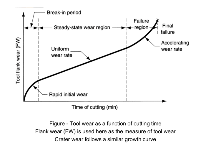
Failure of tools due to tool wear is typical, but can be analyzed and addressed with tool monitoring. The wear generally occurs over time and is a gradual failure in a cumulative process that affects tool life. Tool wear will also vary depending on tool shape, depth, cutting fluid, and cutting speed. This impacts the sharpness and effectiveness of the tool and means that some tools can subtly change shape.
Tool wear depends on many variables. Type of equipment, hardness of blank feedstock, number of operations performed on the part, force applied for each task, and other variables will contribute to tool wear. Because of these variables, tool wear will take many forms, including:
Depending on end-use, metal feedstock in workpieces used in CNC machining will vary in purity. When impurities exist, they can result in a build-up of edge fragments. These fragments can abrade the tool, reducing its sharpness and effectiveness over time. Abrasion is a mechanical form of wear that occurs most often at low spindle speed.
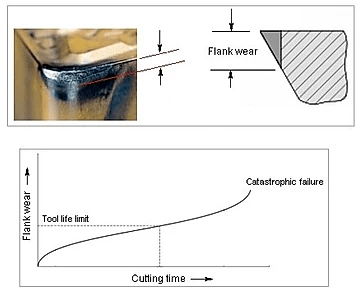
Flank wear occurs parallel to the cutting edge and can result in cutting edge failure. As workpieces encounter abrasive and adhesive wear, high temperatures form and impact the tool and performance characteristics of the workpiece. As flank wear increases, the speed of the cut must be increased as well.
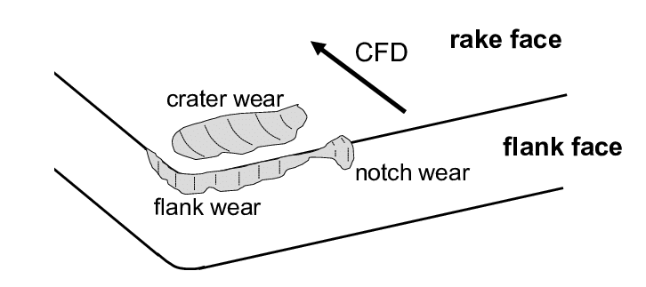
As tools impact the work face at high speed, chips form and damage the tool's rake face. This chip flow across the face leaves a divot, or crater, like a scar. The formation of craters is a typical type of tool wear that may not impact the tool quality unless it directly deforms the cutting surface. Crater wear generally occurs near the cutting edge.
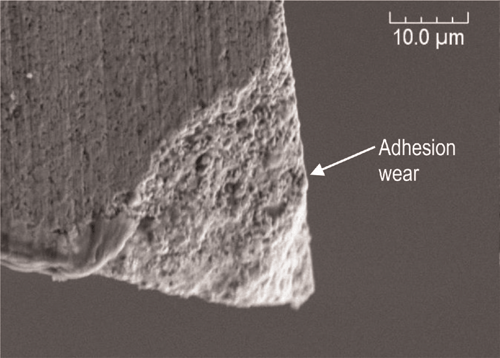
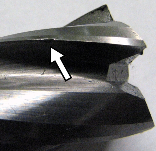
Because tools and workpiece friction cause high temperatures, adhesion wear can occur. Here, chips flowing over the face of the tool may bond with the tool face itself, like a spot-welding effect. This may also impact the dimensional accuracy of the workpiece itself. Adhesion wear may occur more often if the wrong fluid or wrong amount of fluid is used.
Detecting tool wear may be done manually by the observation of machinists and operators or in an automated fashion, using a tool monitoring system. Historically, tool wear has been identified only after it’s impact has been noticed, such as the realization that the tool is producing poor quality parts. However, with the development of automated software solutions, stakeholders are better able to identify tool wear and tool failure as soon as it occurs, or even predict and prevent it from happening altogether. Some of the approaches for detecting tool wear include:
Chipping occurs on the cutting face and creates a rough or marred cutting edge. It may result from an improper machine setup or because the tool holder isn't correctly secured. This can also occur in larger workpieces where chips may be carried up to a half rotation before being impacted by fluid.
CNC machined pieces generate excessive heat between the tool and the workpiece. Managing this heat ensures the correct speed, proper tool set up for tool holders, and the correct amount of fluid. If the heat generated is too high or too low, or if temperature variations swing quickly from cut to cut, it can affect the performance characteristics of the workpiece metal. This can cause the formation of cracks that are evenly spaced and perpendicular to the turning tool’s cutting edge.
Sometimes, the increased cutting forces between the tool and the workpiece can be too great to overcome. This force causes the sudden and complete loss of the tool and damage to the workpiece and perhaps the machine itself. Causes for a fracture may lie in settings for depth of cut, speed, or feed of material. Hot spots along the workpiece can also cause fracture by dulling the tool until it fails. Preventing tool breakage avoids safety concerns and avoids downtime events.
When the tool contacts the workpiece's shoulder, the rubbing of the two pieces can create a chemical reaction on the tool. The result creates both abrasion and adhesion and can lead to flank wear. If the wear is excessive, it may lead to complete tool failure.
Plastic deformation is a thermal issue when the material in the cutting tool is softened. If the workpiece material grade is higher than the tool's, the tool can change shape or lose sharpness. This damage can be avoided by understanding the tool hardness in relation to the material hardness and its inherent performance characteristics.
Failure occurs when the tool breaks or fractures altogether. Preventing tool breakage and even catastrophic failure are possible by ensuring the proper speed settings, cutting depth, and force. It also requires using the appropriate fluid. Failure can also be detected when abnormal vibration or noise is present, indicating a tool holder or setting out of spec.
Different metal feedstocks for workpieces may have different performance characteristics. They may be softer or harder depending on the metal. When the metal is softer, an annealing effect can occur where the soft, semi-melted metal adheres to the cutting tool. If the edge builds up too much, the tool can fail. Proper speed and fluid can reduce or eliminate this issue.
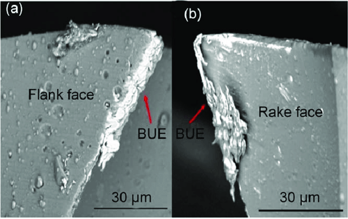 BUE (Built-up Edge) examples on faces of tool. (Source)
When tools begin to reach the end of their lifecycle, or when an event has impacted them, the wear on the tool can create specific wear effects. These effects influence the quality of the parts produced, the efficiency of the equipment, or the downtime associated with operator intervention. The importance of understanding the effects of tool wear is that they can be used to develop thresholds and algorithms for detecting and preventing tool wear in the future.
Tool wear effects can include:
As tool wear builds, increased cutting force may be required to compensate. There will be acceptable tolerance increases for both the tool and the workpiece. But if the wear is significant, the force could exceed acceptable tolerance and require changing.
Metal-to-metal friction from cutting, drilling, and other tasks within the CNC machine will always create high temperatures. If the cutting fluid is too low or not the correct type, a higher temperature can result. Temperature can also rise if the cutting depth is too severe or if the feed is too high. Finally, higher speed can also contribute to even more heat.
As wear occurs, the accuracy of the part decreases. There will be acceptable tolerances for any workpiece. But a single type of tool wear can increase to the point that the part goes out of spec for that cutting activity, causing loss of the part. Multiple types of wear can coincide, cascading the deformation and, therefore, the accuracy of the part. This can create a major quality issue as parts will either need to be scrapped or reworked. Effectively manaing tool wear and understanding when failure will occur is an important part of maintaining high quality in an efficient manner.
Different types of tool wear, the differential hardness between tooling and workpiece, and repeatedly high to low temperatures can cause reduced tool life. These factors can be managed based on experience and training and an operator's knowledge of the workpiece and tool material. But they can also be monitored by advanced tool monitoring software from MachineMetrics. Decreased tool life is a controllable issue with the correct automated monitoring in place.

The more critical the tool wear, the greater the impact on the surface finish. Dull tools may cause uneven or jagged cut faces on the workpiece. And drilling or cutting may cause surface build-up or increases in wear land, contributing to chipping and cratering, affecting the surface finish. Especially in high precision machining, this can develop severe quality issues, meaning pieces will either need to be re-worked or scrapped.
Cutting and machining are expensive production technologies. The high cost of equipment, operator training, high-quality tooling, and proper material selection of workpiece feedstock can be impacted by tool wear. Each life span reduction of a tool and each scrapped workpiece adds cost to the run and reduces profit margin. And worn tools are also a danger to the operator and machine, risking even higher repair costs.
Worn tools will exhibit observable and predictable behavior in many but not all instances. Temperature-increased cutting force and other wear factors may create signs that manifest as vibration or noise. Learning these signs can help operators adjust to reduce wear.
As discussed above, there are many types of tool wear. Some are mechanical; others can be created through equipment settings or operator error. And some, such as temperature management, require a skilled dance to create the best environment to reduce wear. It is critical that operators know the types of tool wear and that each can be caused by different circumstances that occur alone or in combination.
High temperature in a metal-to-metal machining process is inevitable. But temperature management is critical. If done correctly, most of the heat is removed with the chip fly off.
With so much heat being transferred from the chip flyoff, the proper type and amount of cutting fluid must be used to remove the chips and help direct the excess heat away. Understanding the material of the workpiece and tool and the specifications, speed, and feed rate will determine the application rate of coolant during cutting.
Metals have vastly different performance characteristics. Hardened metals can create greater temperature and require more force, while softer metals with lower melting points can have a higher built-up edge. Knowing the performance characteristics of the feedstock, the quality and characteristics of the tool, and even the age and capabilities of the machine can help you choose the right tool for the suitable metal.
Tool selection is critical and should include sharpness, tool geometry, coating, and function considerations. This selection also requires understanding equipment types and age and tool holding capabilities, depending on feedstock.
Traditionally, tool wear was experiential. In a machining operation, operators had to undergo years of training to learn by "feel" and observation when a tool was experiencing excessive wear. And many settings and parameters were determined experimentally or were simply accepted based on schedules provided by machine tool OEMs. But, this approach is highly inaccurate, resulting in poor quality parts, unused tool life, and excessive downtime.
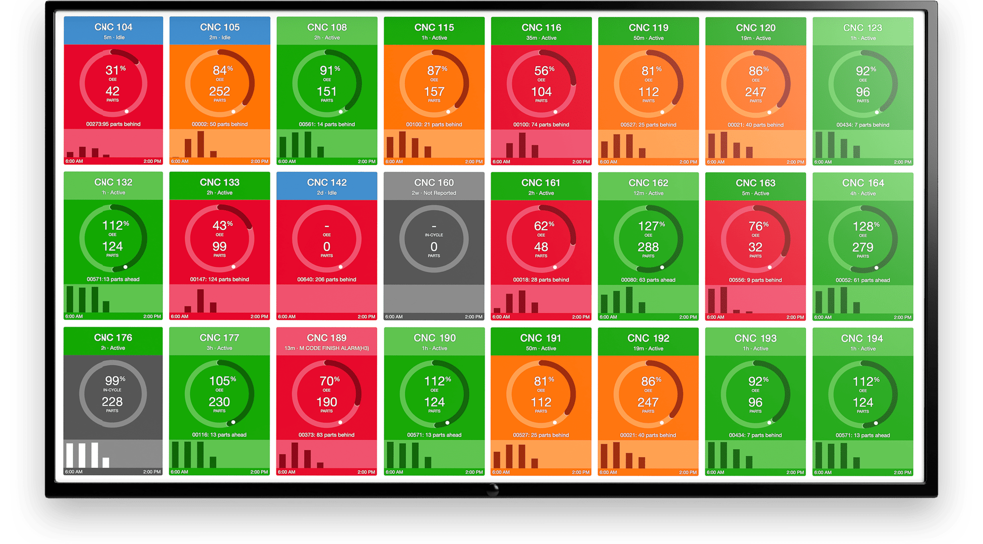
Fortunately, reducing and managing tool wear can be automated quickly and efficiently with MachineMetrics Tool Monitoring system. Settings can be monitored to a degree not possible with human intervention, and variations are reported through intuitive dashboards that display machine conditions accurately. MachineMetrics can even analyze the frequency of signals within the machine to predict tool failure.
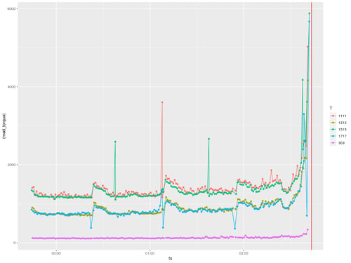
.png?width=750&height=500&name=MachineMetrics%20Tool%20Anomaly%20Detection%20(1).png) MachineMetrics Tool Anomaly Detection enables manufacturers to leverage AI to quickly diagnose, predict, and avoid failures on machine tools.
MachineMetrics Tool Anomaly Detection enables manufacturers to leverage AI to quickly diagnose, predict, and avoid failures on machine tools.
The insights and analysis offered by the software can deliver immediate benefits for optimizing processes, addressing undetected problems, and prescribing solutions to reduce cost, increase quality, and ramp-up capacity. To find out how MachineMetrics can deliver solutions to help you manage and control tool wear and get the best out of your tooling and equipment, book a demo today.
BC Machining, a manufacturer of fabricated metal parts, was producing such large quantities of scrap that they were forced to run their machines at 200% capacity just to hit their production goals. With no insight into when tools were worn or about to break, BC Machining accumulated significant costs from producing scrap and replacing broken tooling.
To prevent scrap production and maximize tool life, they partnered with MachineMetrics. Read our case study to learn how BC Machining virtually eradicated scrap from tool wear, significantly reduced their changeover times, and saved $72k per machine annually. Read the complete case study.

Ready to empower your shop floor?
Learn More
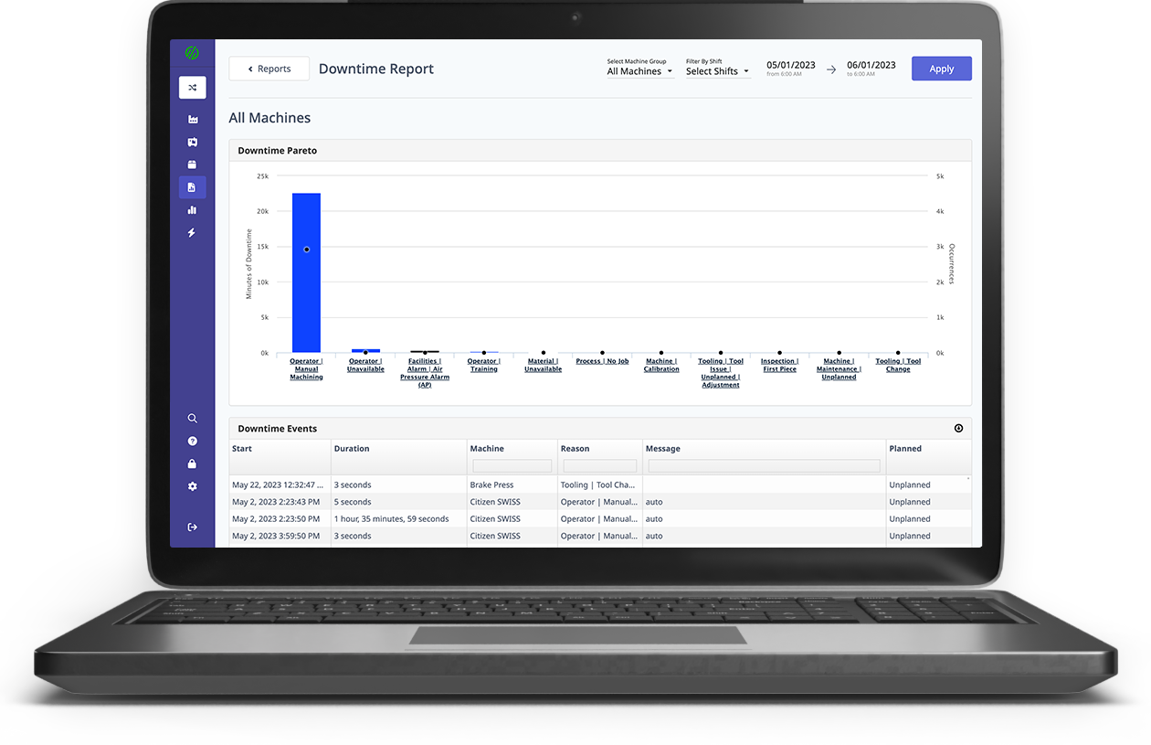
.png?width=1960&height=1300&name=01_comp_Downtime-%26-Quality_laptop%20(1).png)

.gif)


Comments